 手机版|
手机版|

 二维码|
二维码|-
- 产品
- 通用机械设备 行业专用设备 电气与能源设备 仪器仪表 网络安防/通信广电 电脑/办公设备 原辅料/初加工材料 建材与装饰材料 五金零部件/备品件 电子元器件 电工电料/线缆照明 综合工具 MRO消耗易耗品 文教办公用品 交通运输/汽摩/配件 生活消费
- 企业
- 通用机械设备 行业专用设备 电气与能源设备 仪器仪表 网络安防/通信广电 电脑/办公设备 原辅料/初加工材料 建材与装饰材料 五金零部件/备品件 电子元器件 电工电料/线缆照明 手动工具 MRO消耗易耗品 文教办公用品 交通运输/汽摩/配件 生活消费 商务服务

![]()


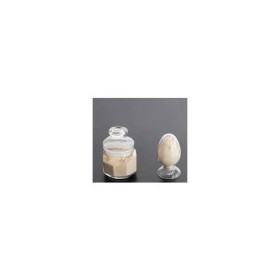
JNFP40N120M 工控用 IGBT模块替代FP40R12KT3

- ¥: 158.00元/
- 起订量:5
- 可售数量: 10000
- 支持批量采购
- 发布时间:2019-03-03 21:47
青岛佳恩半导体有限公司
- 店铺等级:

- 旺铺店长: jiaensemi
- 服务保障:暂未签署消保协议
- (什么是消费者保障协议)
- 认证类型:
- 身份认证: [诚信档案]
- 状态:[离线] [加为商友] [发送信件]
资料信息
- 实名认证
- 信用认证
- 商品合格
认证信息


- 产品详情
- 联系方式
- 产品评价
- 供货总量:10000
- 发货期限:自买家付款之日起 天内发货
- 所在地:山东 青岛市
品牌:青岛佳恩型号:JNFP40N120M类型:绝缘栅型场效应管/MOS场效应管沟道类型:N型沟道导电方式:增强型适合频率:高频封装外形:CER-DIP/陶瓷直插材质:N-FET硅N沟道工作电压:40AV工作电流:1200VA
JNFP40N120M
IGBT Module
Features:
l IGBT Inverter Short Circuit Rated 10μs
l IGBT Inverter Low Saturation Voltage
l Low Switching Loss
l Low Stray Inductance
l Lead Free, Compliant With RoHS Requirement
Applications:
l Industrial Inverters
l Servo Applications
IGBT-Inverter
Absolute Maximum Ratings(TC= 25℃ unless otherwise specified)
Symbol | Description | Value | Units | |
VCES | Collector-Emitter Blocking Voltage | 1200 | V | |
VGES | Gate-Emitter Voltage | ±20 | V | |
IC | Continuous Collector Current | TC= 80℃ | 40 | A |
TC= 25℃ | 80 | A | ||
ICM(1) | Peak Collector Current Repetitive | TJ= 150℃ | 80 | A |
tSC | Short Circuit Withstand Time | TJ= 150℃ | >10 | μs |
PD | Maximum Power Dissipation (IGBT) | TC= 25℃ TJmax=150℃ | 255 | W |
Characteristic Values(TJ= 25℃ unless otherwise specified)
Symbol | Description | Test Conditions | Min. | Typ. | Max. | Units | |
ICES | Collector-Emitter Leakage Current | VGE= 0V, VCE = VCES | TJ= 25℃ |
|
| 1 | mA |
IGES | Gate-Emitter Leakage Current | VGE= VGES, VCE= 0V | TJ= 25℃ |
|
| 200 | nA |
VGE(th) | Gate-Emitter Threshold Voltage | IC= 1 mA, VCE= VGE | 4.5 | 5.2 | 6.5 | V | |
VCE(sat) | Collector-Emitter Saturation Voltage | IC= 40A , VGE = 15V | TJ= 25℃ |
| 1.90 | 2.10 | V |
TJ= 125℃ |
| 2.20 | 2.40 | V | |||
Cies | Input Capacitance | VCE= 25V, VGE= 0V , f=1MHz |
| 2.2 |
| nF | |
Coes | Output Capacitance |
| 0.21 |
| nF | ||
td(on) | Turn-on Delay Time | VCC= 600V, IC= 40A, RG= 33??, VGE=±15V , Inductive Load, TJ= 25℃ |
| 115 |
| ns |
tr | Rise Time |
| 70 |
| ns | |
td(off) | Turn-off Delay Time |
| 475 |
| ns | |
tf | Fall Time |
| 285 |
| ns | |
Eon | Turn-on Switching Loss |
| 6.2 |
| mJ | |
Eoff | Turn-off Switching Loss |
| 2.4 |
| mJ | |
Ets | Total Switching Loss |
| 8.6 |
| mJ | |
td(on) | Turn-on Delay Time | VCC= 600V, IC= 40A, RG= 20??, VGE=±15V, Inductive Load, TJ= 125℃ |
| 105 |
| ns |
tr | Rise Time |
| 75 |
| ns | |
td(off) | Turn-off Delay Time |
| 505 |
| ns | |
tf | Fall Time |
| 445 |
| ns | |
Eon | Turn-on Switching Loss |
| 8.1 |
| mJ | |
Eoff | Turn-off Switching Loss |
| 3.9 |
| mJ | |
Ets | Total Switching Loss |
| 12.0 |
| mJ | |
Qg | Internal Gate Resistor | VCE= 600V, IC= 40A, VGE= -15V ~ +15V |
| 445 |
| nC |
RBSOA | Reverse Bias Safe Operating Area | IC= 80A ,VCC= 960V, Vp =1200V, Rg = 15??, VGE=+15V to 0V, TJ=150°C | Trapezoid |
| ||
SCSOA | Short Circuit Safe Operating Area | VCC= 600V, VGE= 15V, TJ= 150℃ | 10 |
|
| μs |
Diode-Inverter
Absolute Maximum Ratings(TC= 25℃unless otherwise specified)
Symbol | Description | Value | Units |
VRRM | Repetitive Peak Reverse Voltage | 1200 | V |
IF | DC Forward Current | 40 | A |
IFRM | Repetitive Peak Forward Current | 80 | A |
Characteristic Values
Symbol | Description | Conditions | Min. | Typ. | Max. | Units | |
VF | Forward Voltage | IF=40A, VGE= 0V | TJ= 25℃ |
| 2.1 |
| V |
TJ= 150℃ |
| 2.1 |
| ||||
Irr | Peak Reverse Recovery Current | IF=40A, di/dt = 835A/μs, Vrr= 600V, VGE= -15V | TJ= 25℃ |
| 35 |
| A |
TJ= 125℃ |
| 45 |
| ||||
Qrr | Recovered Charge | TJ= 25℃ |
| 3.9 |
| μC | |
TJ= 125℃ |
| 6.0 |
| ||||
Erec | Reverse Recovery Energy | TJ= 25℃ |
| 0.7 |
| mJ | |
TJ= 125℃ |
| 1.3 |
| ||||
Diode-Rectifier
Absolute Maximum Ratings(TC= 25℃ unless otherwise specified)
Symbol | Description | Value | Units | |
VRRM | Repetitive Peak Reverse Voltage | TJ=25℃ | 1800 | V |
IFRMSM | Forward Current RMS Maximum Per Diode | TJ=80℃ | 50 | A |
IRMSM | Maximum RMS Current At Rectifier Output | TC= 80℃ | 60 | A |
IFSM | Surge Current @tp=10 ms | TJ=25℃ | 315 | A |
TJ=150℃ | 270 | |||
I2t | tp=10 ms | TJ=25℃ | 500 | A2s |
TJ=150℃ | 370 | |||
Characteristic Value
Symbol | Description | Conditions | Min. | Typ. | Max. | Units | |
VF | Forward Voltage | IF=40A (tested on top of terminals) | TJ= 25℃ |
| 1.10 | 1.30 | V |
TJ= 125℃ |
| 1.05 |
| ||||
IGBT-Brake-Chopper
Absolute Maximum Ratings(TC= 25℃ unless otherwise specified) | ||||
Symbol | Description | Value | Units | |
VCES | Collector-Emitter Blocking Voltage | 1200 | V | |
VGES | Gate-Emitter Voltage | ±20 | V | |
IC | Continuous Collector Current | TC= 80℃ | 15 | A |
TC= 25℃ | 30 | A | ||
ICM(1) | Peak Collector Current Repetitive | TJ= 150℃ | 30 | A |
PD | Maximum Power Dissipation Per Leg | TC= 25℃ TJmax=150℃ | 180 | W |
Characteristic Values
Symbol | Description | Test Conditions | Min. | Typ. | Max. | Units | |
ICES | Collector-Emitter Leakage Current | VGE= 0V, VCE = VCES | TJ= 25℃ |
|
| 1 | mA |
IGES | Gate-Emitter Leakage Current | VGE= VGES, VCE= 0V | TJ= 25℃ |
|
| 200 | nA |
VGE(th) | Gate-Emitter Threshold Voltage | IC= 1 mA, VCE= VGE | 4.5 | 5.2 | 6.5 | V | |
VCE(sat) | Collector-Emitter Saturation Voltage | IC= 15A , VGE = 15V | TJ= 25℃ |
| 1.90 | 2.10 | V |
TJ= 125℃ |
| 2.20 |
| V | |||
Cies | Input Capacitance | VCE= 25V, VGE= 0V , f=1MHz |
| 1.5 |
| nF | |
Coes | Output Capacitance |
| 0.13 |
| nF | ||


- ·爱普生压电写真机喷头厂家资讯2025-08-18
- ·广州水泥电线杆厂2025-08-18
- ·生产尼龙检测筛 各种尺寸分样筛2025-08-18
- ·厂家生产冲孔板 304材质圆孔板2025-08-18
- ·厂家供应平纹编织不锈钢网 筛网2025-08-18
- ·大口径金属软管 耐磨金属软管 304不2025-08-18
- ·定制不规则不锈钢焊接网片生产厂家2025-08-18
- ·清洗外框加工生产厂家 网篮2025-08-18
- ·供应底部200目丝网不锈钢分样筛2025-08-18
- ·激光切割各种直径不锈钢烧结圆片2025-08-18
- ·PIM模块FP10R12W1T7、FP25R12W1T7福建/厦门市
- ·原装正品 一级代理 华晶场效应管 华广东/深圳市
- ·场效应管 CEU4201 CEU4301 CEU6355广东/深圳市
- ·代理场效应管MOS管(仙童FAIRCHILD IR广东/东莞市
- ·经销进口拆机IRF740场效应管质量保证广东/深圳市
- ·士兰微代理 SVF8N60 场效应管广东/佛山市
- ·4N60场效应管广东/深圳市
- ·N沟道场效应管FQP7N80C铁头原装正品广东/深圳市
- ·专业生产 30N40、G30N60A4D FAIRCHIL广东/汕头市
- ·2SK2648 场效应管 K2648广东/深圳市
- ·东莞市凤岗新广晟杰利模具科技有限公广东/东莞市
- ·淄博悦达保温建材有限公司山东/淄博市
- ·肥城市本森自动化设备厂(个体工商户山东/泰安市
- ·北京新渠道科技中心北京
- ·深圳市联鑫德诚科技有限公司广东/深圳市
- ·深圳市艾瑞斯仪器有限公司广东/深圳市
- ·腾龙娱乐公司上分客服{电话}上海
- ·新盛游戏公司{上分客服}上海
- ·腾龙娱乐游戏有限公司{上分客服电话}上海
- ·新盛娱乐游戏公司{上分客服}上海

-
徐旭
18561536907
- 友情链接
- 综合站
- 企业站
- 协会展会

